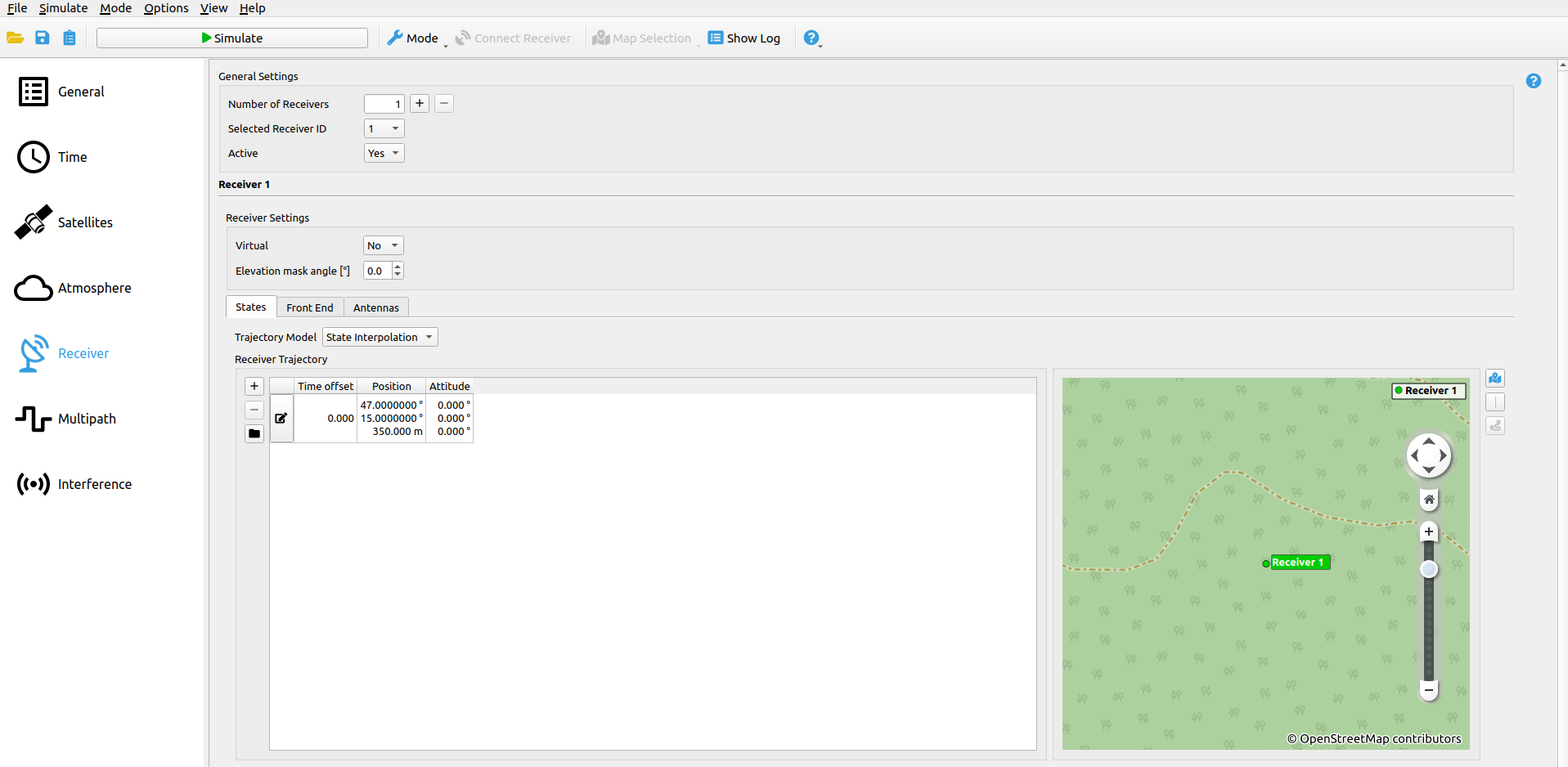
# Receiver
The Receiver settings cover the following receiver based options:
- Receiver Path
- Front-End settings
- Antennas
# General Receiver options
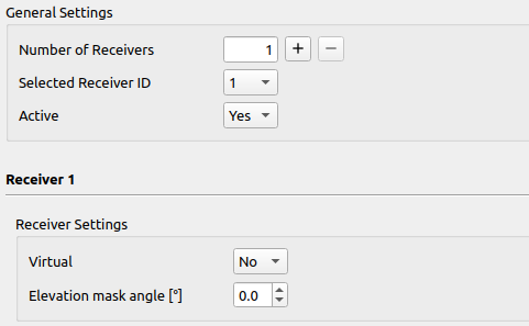
| Parameter | Description |
|---|---|
| Active | If enabled, the receiver will be simulated (at least one receiver must be active). |
| Virtual | If enabled, the receiver will be simulated but no authentic signals will be generated for it (only interference signals). |
| Elevation Mask angle | The receiver's elevation mask can be set here. All satellites with an elevation lower than the set elevation mask angle are not visible and thus are ignored by the simulation (only for observations - the satellite orbits are computed independently from receiver settings). |
# Receiver States
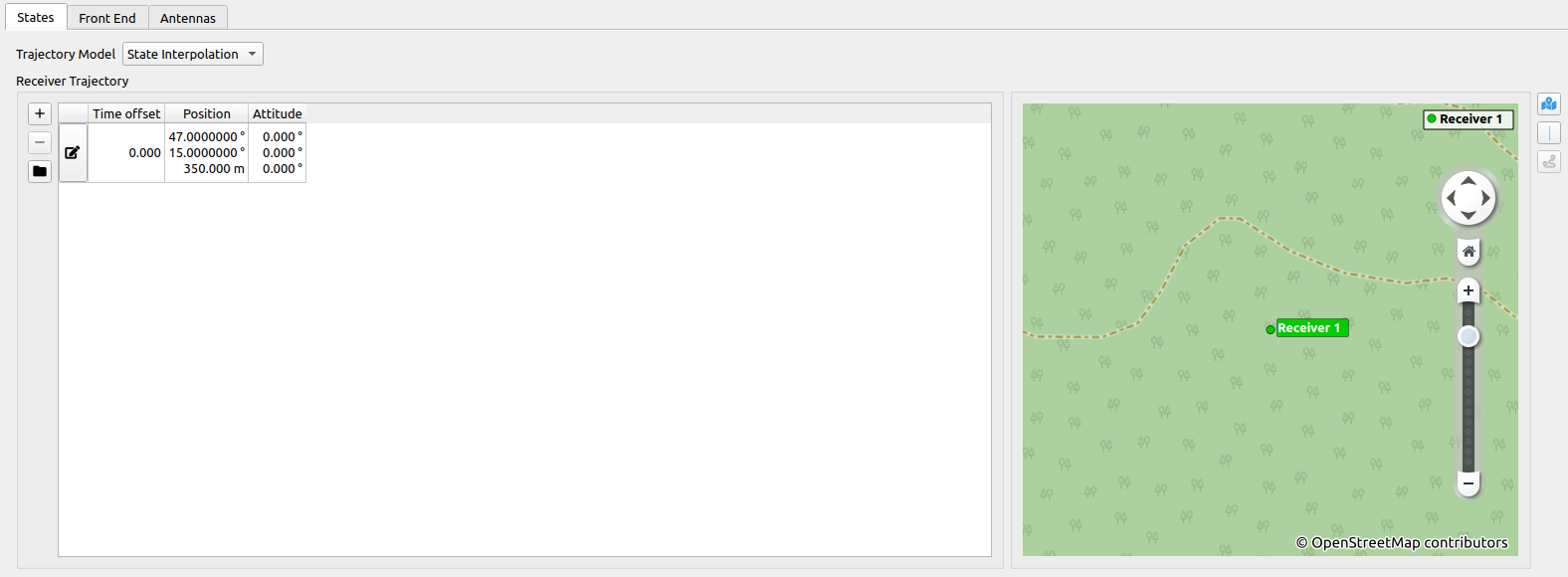
Additional Information:
- See Trajectory Definition for details.
- See Trajectory Map and Routing for details on how to use the automatic map routing capabilities.
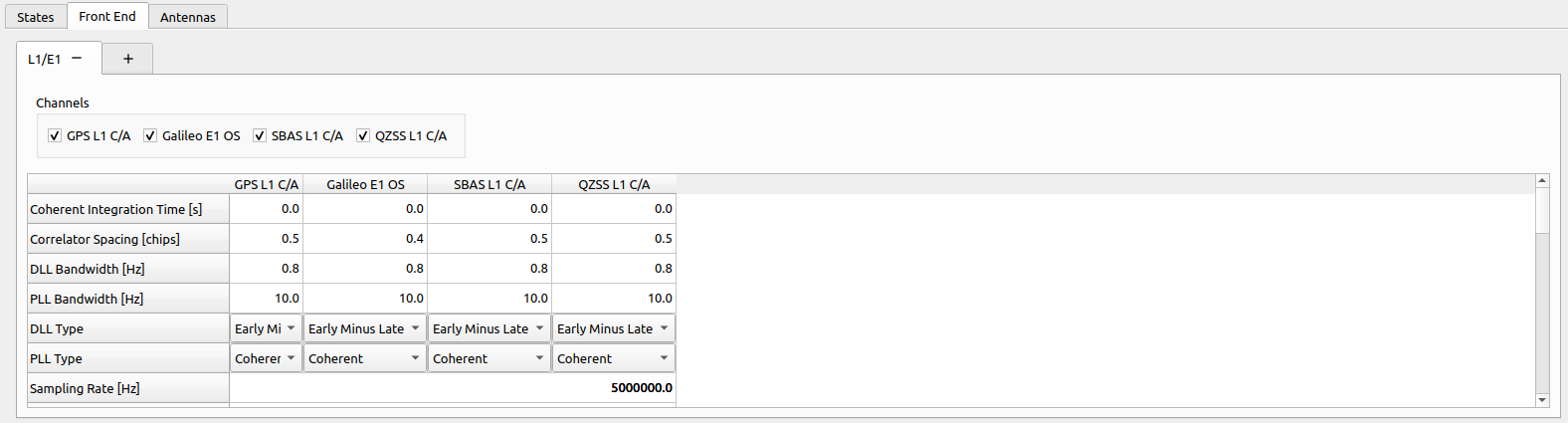
# Front-Ends
NOTE
If GIPSIE® mode is set to RTX, no Front-End settings are available, since it is handled automatically by the IZT S1000 hardware (see RTX Mode).
Within the table, the bandwidth of the front-end, the IF, as well as the code dependent parameters of the tracking loops within a receiver can be set (coherent integration time, chip spacing, bandwidth of the DLL and PLL as well as the according types). The GIAT module computes the influence of all simulated signals on the tracking loops and furthermore on the raw observations by utilization of the spectral separation coefficient (SSC).
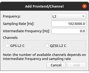
A channel can be added by selecting  on the most right tab. This opens the Add Front-End/Channel dialog.
# Channel depending options
| Parameter | Description |
|---|---|
| Coherent Integration Time [s] | Coherent integration time of the correlation. |
| Correlator Spacing [chips] | Spacing between two consecutive correlators. |
| DLL Bandwidth [Hz] | Filter bandwidth of the Delay Lock Loop. |
| PLL Bandwidth [Hz] | Filter bandwidth of the Phase Lock Loop. |
| DLL - Type | Available values:
|
| PLL - Type | Available values:
|
# Front-End options
| Parameter | Description |
|---|---|
| Sampling Rate [Hz] | The sampling rate of the simulated receiver. |
| Intermediate Frequency [Hz] | The used IF within the receiver. |
| Seed Number of Random Signal | Seed for random generator specifying the initial phase of the signal. |
# Local Oscillator options
| Parameter | Description |
|---|---|
| LO Phase Noise [rad] | σ of phase noise |
| LO Seed Number of Phase Noise | Seed for phase noise generation |
| LO Clock Jitter [s] | σ for clock jitter |
| LO Seed Number of Clock Jitter | Seed for clock jitter generation |
# LNA options
| Parameter | Description |
|---|---|
| LNA Noise Figure [dB] | Noise figure of the LNA. |
| LNA Gain [dB] | Gain (amplification) of LNA. |
# Filter options
| Parameter | Description |
|---|---|
| Filter Active | If enabled, a front-end filter will be simulated. |
| Filter Order | Filter order of low-pass front-end filter. |
| Filter Bandwidth [Hz] | Filter bandwidth. |
| Filter Window Type | Available values:
|
# Blanking options
| Parameter | Description |
|---|---|
| Blanking Active | If enabled, blanking within the front-end will be simulated. |
| Blanking Threshold | Threshold above which all amplitudes will be set to zero. |
# Saturation options
| Parameter | Description |
|---|---|
| Saturation Active | If enabled, saturation within the front-end will be simulated. |
| Saturation Threshold | Threshold above which all amplitudes will set to the maximum value. |
# VGA options
| Parameter | Description |
|---|---|
| VGA Gain Range [dB] | Range for the variable gain amplifier. |
| VGA Length | VGA length in samples. |
| VGA Reference Power [dB] | Reference power value for VGA. |
# Decimation options
| Parameter | Description |
|---|---|
| Decimation Active | If enabled, decimation within the front-end will be simulated. |
| Decimation Factor | Integer factor used for decimation level. |
# ADC options
| Parameter | Description |
|---|---|
| ADC Quantization Levels | Number of quantization levels (has to match number of bits of output configuration). |
| ADC Gain [dB] | Gain of the ADC. This settings is only used, when Use AGC is set to false. |
| Use AGC | If enabled, an adaptive gain control will be simulated. |
| AGC length | Number of samples considered by AGC. |
# Antennas
Every receiver can have an unlimited number of antennas defined, all of which are seperatly simulated as IF or RF output.
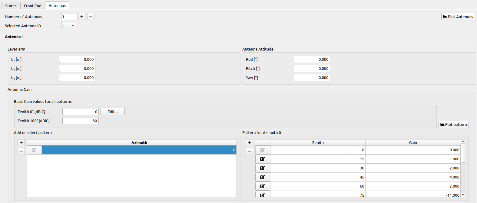
# Lever Arm and Antenna Attitude

Every antenna has a lever arm and an attitude independent from the receivers attitude. For the detailed definition of frames and attitude computation see Receiver Attitude and Antennas.
# Antenna Gain
Within the Antenna Gain parameters tab, an arbitrary antenna pattern can be configured. It offers the possibility to add a maximum of 360 different patterns for each integer azimuth angle (orientation to north). All antenna patterns use common values of gain for a zenith of 0° as well as 180°.
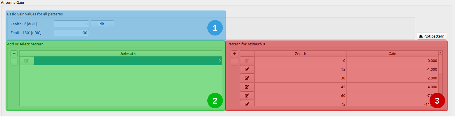
- Basic Gain values: The common gain for an Zenith angle of 0° and 180° can be set here respectively. The pattern is applied for all Azimuths.
- Add or select pattern: The Azimuth for each pattern is presented in this table. The current Azimuth for the table in the highlighted area 3 is selected here. Moreover, additional antenna patterns for other Azimuths can be added/deleted here.
- Pattern for specific Azimuth: The antenna pattern for a singular Azimuth is presented as table. Editing of existing gain values or adding/deleting gain values is possible here.
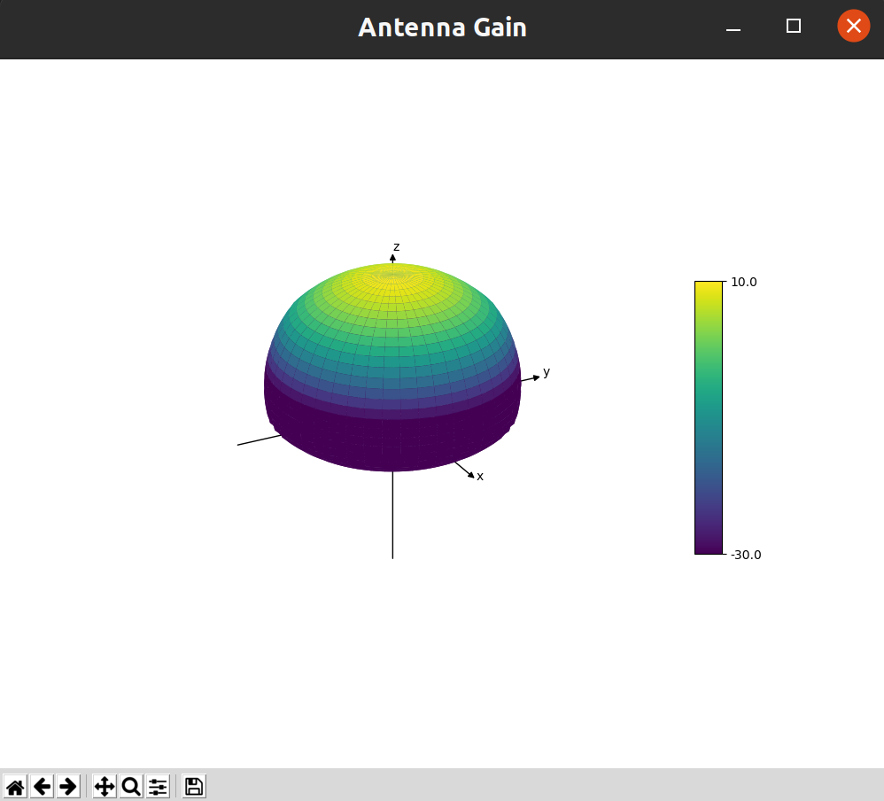
# Plot Pattern
The plot shows the interpolated antenna patterns for each integer Azimuth angle 0°-360° and each Zenith angle 0°-180°.
← Atmosphere Multipath →