# Local Environment
The Local Environment settings cover the following options:
- Multipath Settings
- Jammer Settings
- Spoofer Settings
# Multipath
In case of a receiver operating in a real-world environment, satellite signals are likely to be affected by obstructing and reflecting objects, the later ones inducing multipath signals. Multipath signals of reflected or diffracted satellite signals are always time-delayed compared to direct LOS signals. Thus, several signals of a single satellite arrive at the receiver, decreasing the accuracy of the pseudorange measurement.
The Multipath tab is divided into two different sections:
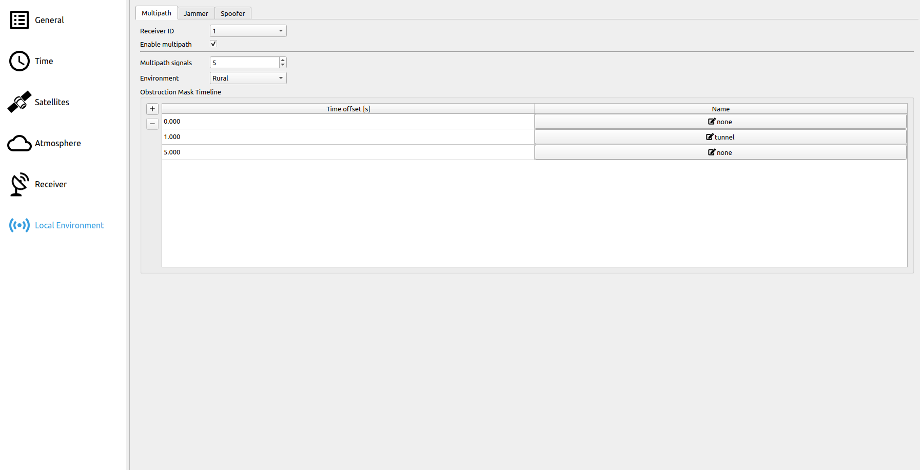
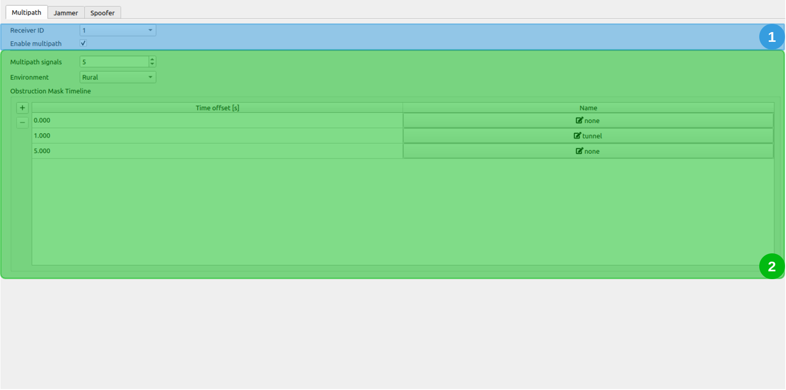
# 1. Receiver Selection

Select the receiver for which multipath should be applied and if the multipath simulation should be enabled.
# 2. Multipath Signals & Obstruction Mask
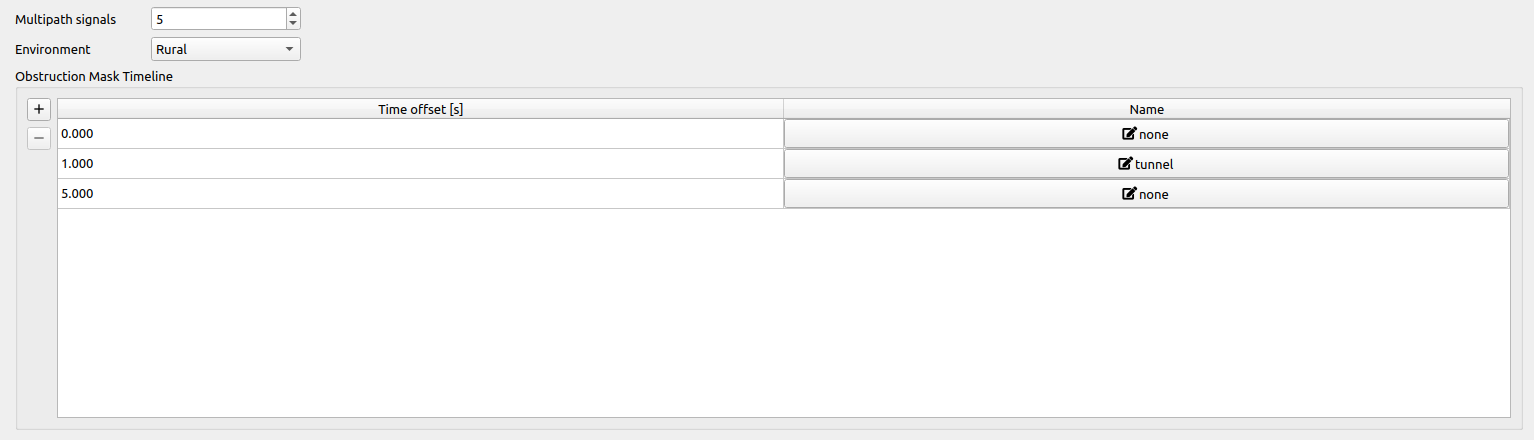
Multipath Signals: Determines the number of signals additionally superimposed on the simulated base signal for all echoes in the Obstruction Mask.
Environment: Possible environments are:
- Rural
- Suburban
- Urban
- Highway
The environment determines the Rayleigh distribution parameters which are a function of the satellite's elevation. The satellite's signal power and a statistical delay (based on the Rayleigh Distribution) are computed based on the Rayleigh parameters and the satellite's orientation relative to the receiver (see Multipath).
Obstruction Mask Timeline: Each row represents an obstruction mask, that is applied to the receiver at the given time offset [s]. The time offset is defined relative to the beginning of the scenario. By clicking on the
 button within the obstruction mask table, a separate dialog allows for editing the currently selected obstruction mask.
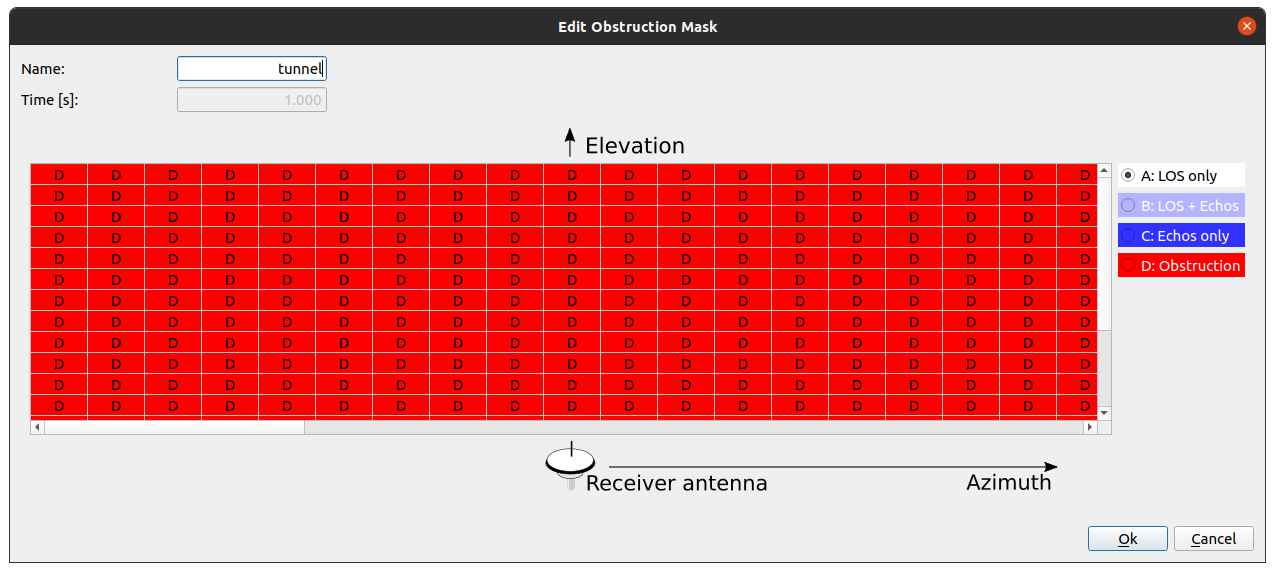 Note that all obstruction masks with the same name share one instance, e.g. if you change the "Tunnel" obstruction mask, all obstruction masks with the name "Tunnel" will be changed in the same way. Each grid point in the displayed azimuth-elevation grid needs to be set to a specific category. Four different types of categories can be selected:
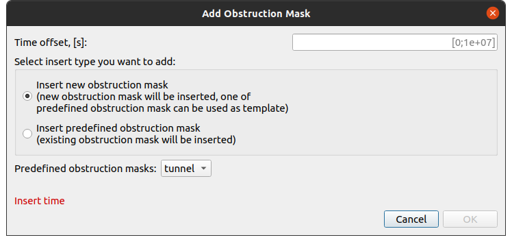
By clicking on the  button a separate dialog allows for adding a new obstruction mask. Here, a predefined obstruction mask (e.g. "Tunnel") can be inserted or a completely new one can be created for a certain time offset.
# Jammer
The Jammer tab displays the options in order to compute the influence of the interferers on the tracking loops (thus the output CNR as well as the noise within the tracking loops is changed). The interference signals are added to the IF signal.
The Jammer tab is divided into three different sections:
- Jammer - Time and Pulsed Interference
- Jammer - Power and Jammer state
- Jammer - Frequency and Jammer Type
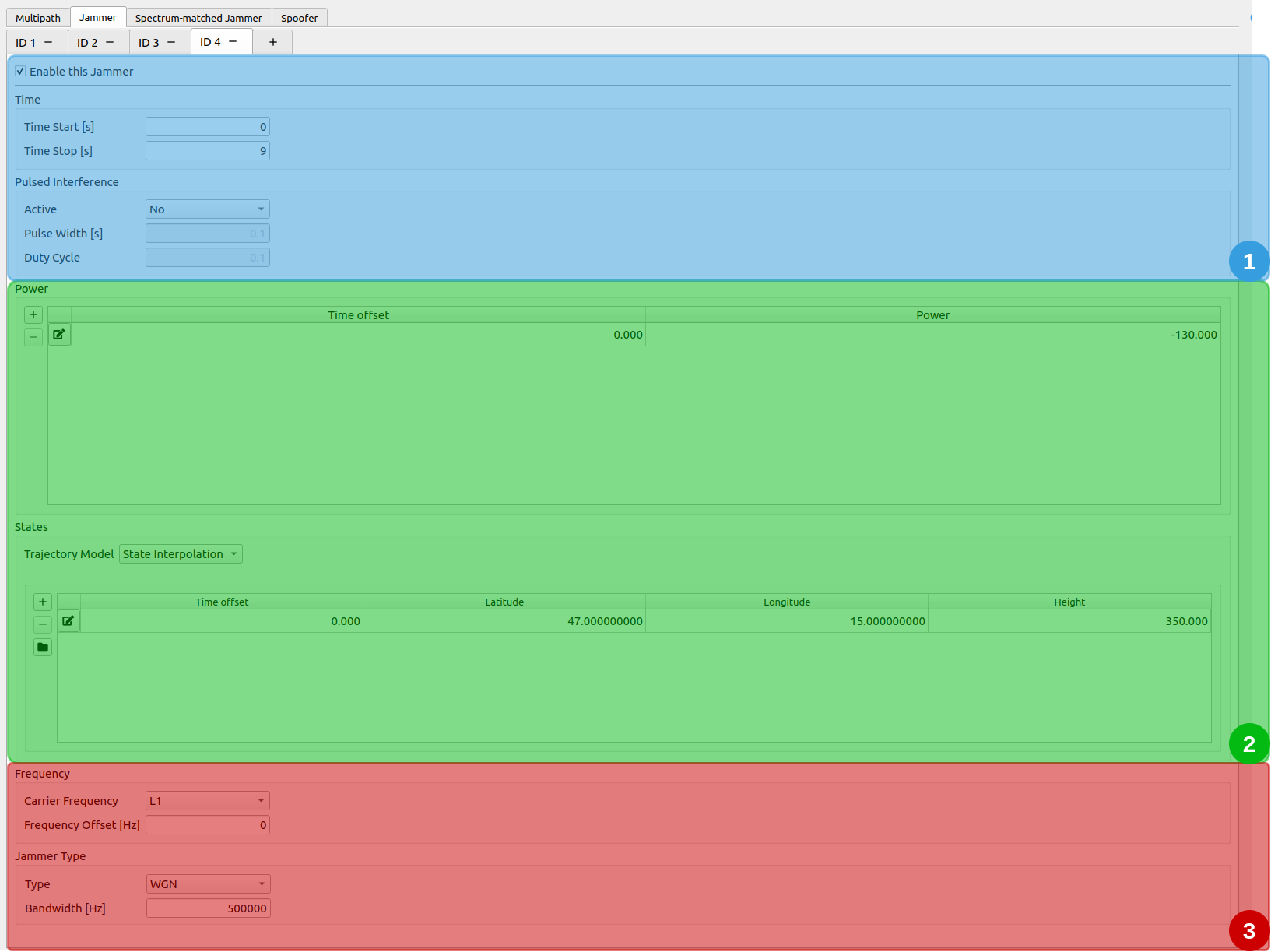
# 1. Jammer - Time and Pulsed Interference
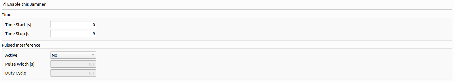
Time: Determines the time-span, where the jammer is simulated and applied.
| Parameter | Description |
|---|---|
| Time start | Time offset [s] relative to the scenario start epoch. |
| Time end | Time offset [s] relative to the scenario start epoch. Has to be larger than Time start. |
Pulsed Interference:
| Parameter | Description |
|---|---|
| Active | Defines, if the jamming signal is pulsed or not. |
| Pulse Width | Defines the width of a single pulse [s] (only available, if pulsed interference is enabled). |
| Duty Cycle | The percentage of time, which is occupied by a pulse (between 0.0 and 1.0). |
# 2. Jammer - Power and Jammer state
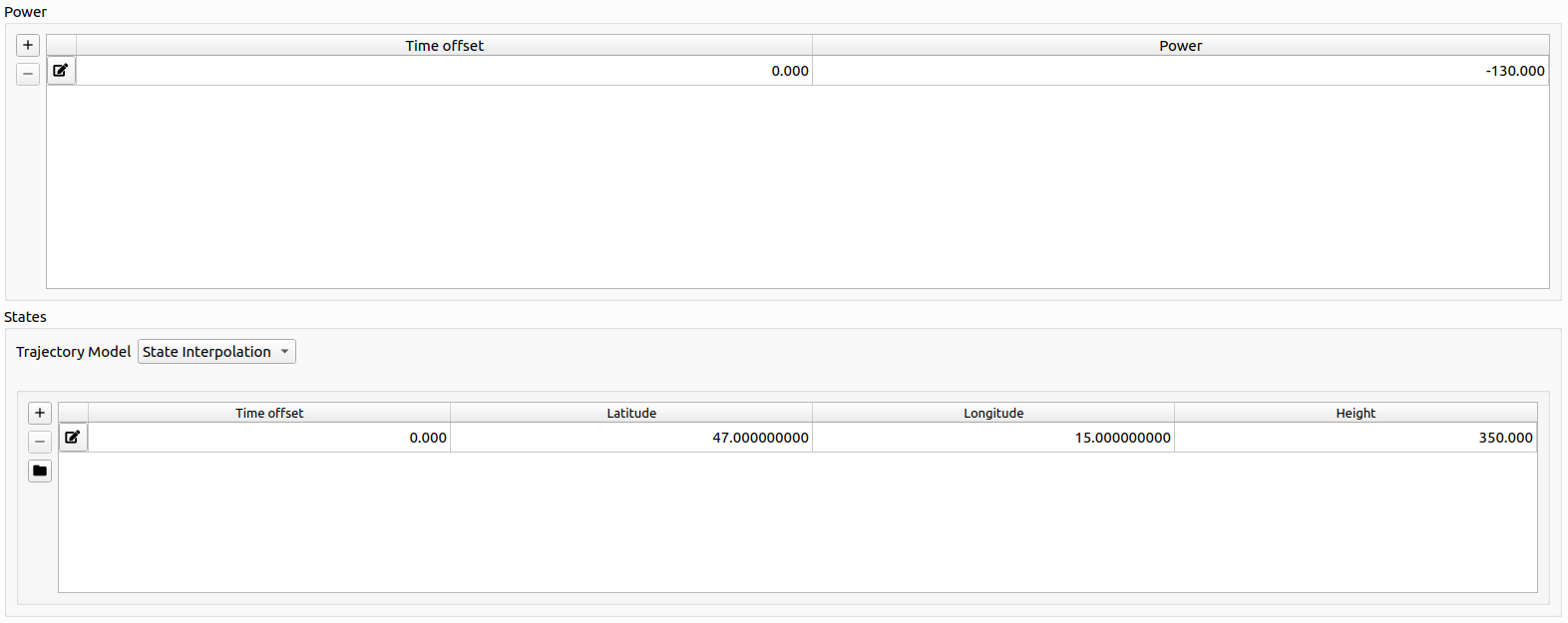
Power:
The table represents a list of time offsets and the corresponding jammer power. Linear Interpolation is applied in between each defined pair of time offset and jammer power.
Jammer state:
The Jammer state. See Trajectory Definition for details.
# 3. Jammer - Frequency and Jammer Type
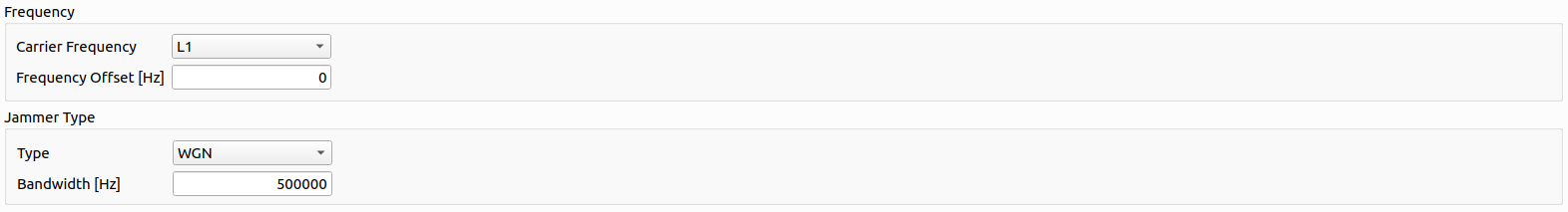
Frequency:
| Parameter | Description |
|---|---|
| Carrier Frequency | The carrier frequency the Jammer is simulated on. See Carrier Frequencies. |
| Frequency Offset [Hz] | The frequency offset from the carrier frequency. |
Note
The Jammer is only simulated if the corresponding channel was selected in the general settings section.
Jammer Type:
The following Jammer Types and their according parameters can be set:
| Type | Parameters |
|---|---|
| AM (Amplitude Modulation) |
|
| FM (Frequency Modulation) |
|
| SCW (Swept Continuous Wave) |
|
| WGN (White Gaussian Noise) |
|
# Spectrum-matched Jammer
The Spectrum-matched jammer tab offers the possibility to add spectrum-matched jamming signals to the simulated signal. Several spectrum-matched jammers can be configured.
The spectrum-matched jammer adds an additional GNSS signal for each satellite in view. Jamming is achieved by transmitting the signal with only the PRN code added to the signal and therefore omitting the navigation message. In addition, each code delay is altered by a synchronization error which is user determinable in contrast to the authentic code delays.
For a detailed description of the mathematical model applied see Spectrum-matched Jammer definition
- Spectrum-matched Jammer - Time and General Options
- Spectrum-matched Jammer - Power
- Spectrum-matched Jammer - State
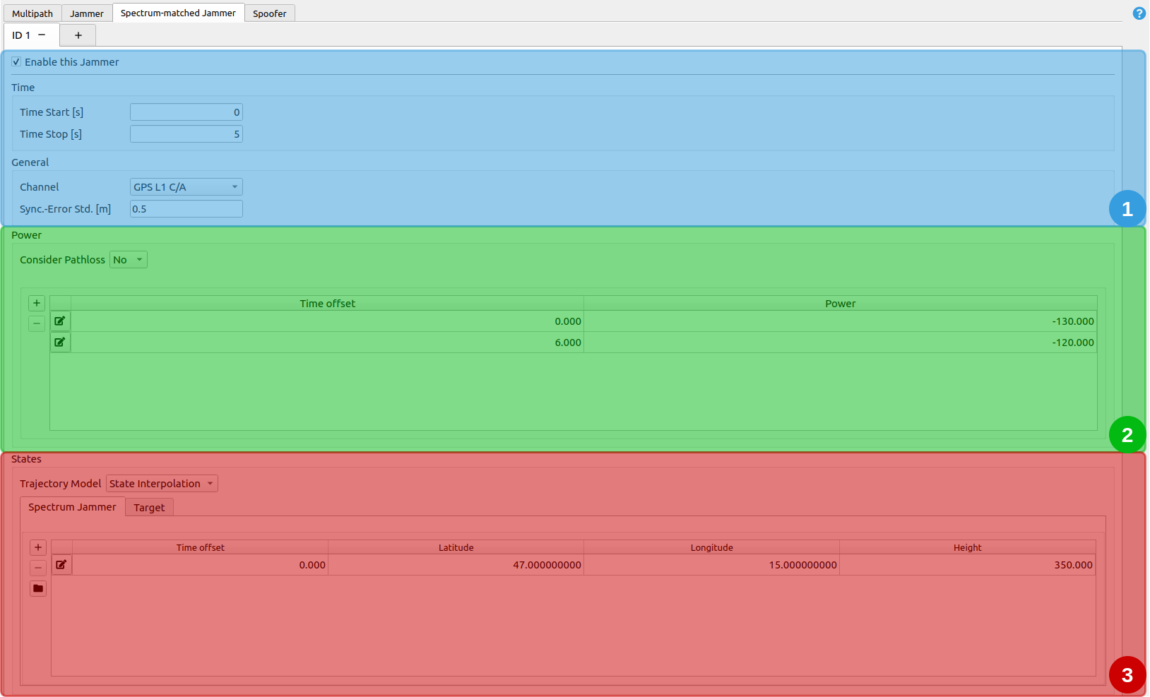
# 1. Spectrum-matched Jammer - Time and General Options
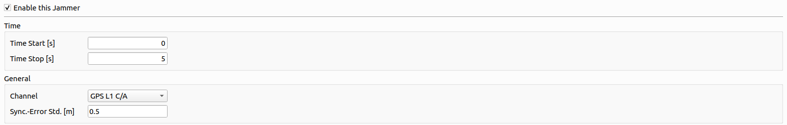
Time: it determines, when the spectrum-matched jammer is simulated.
| Parameter | Description |
|---|---|
| Time start | Time offset [s] relative to the scenario start epoch. |
| Time end | Time offset [s] relative to the scenario start epoch. Has to be larger than Time start. |
General Options:
| Parameter | Description |
|---|---|
| Channel | Determines which channel is jammed. Only one channel per spectrum-jammer can be jammed, and only a channel that is chosen in the General Settings tab can be selected. |
| Synchronization Error Standard Deviation | [m] |
# 2. Spectrum-matched Jammer - Power
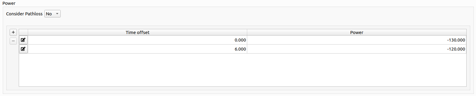
| Parameter | Description |
|---|---|
| Consider Pathloss | The received power of the jamming signal (relative to authentic signals) shall be computed based on path loss or not. |
The table represents a list of time offsets and the corresponding spectrum-matched jammer power in [dB]. Linear Interpolation is applied in between each defined pair of time offset and jammer power. The power is applied relative to the received authentic signal power of the respective satellite.
# 3. Spectrum-matched Jammer - State
Every state is based upon the same trajectory model introduced in Trajectory Definition.
The two trajectory models are
- Spectrum-matched Jammer position
- Target position
For details, go to Spectrum-matched Jammer Trajectory Definition.
# Spoofer
The Spoofer tab offers the possibility to add spoofed GNSS signals to the IF signal. Several spoofers can be configured.
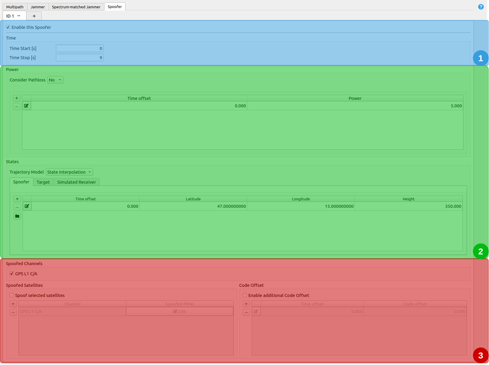
The Spoofer tab is divided into three different sections:
- Spoofer - Time Options
- Spoofer - Power and State
- Spoofer - Channels, spoofed satellites and code offset
# 1. Spoofer - Time Options

Time: it determines, when the spoofer is simulated.
| Parameter | Description |
|---|---|
| Time start | Time offset [s] relative to the scenario start epoch. |
| Time end | Time offset [s] relative to the scenario start epoch. Has to be larger than Time start. |
# 2. Spoofer - Power and State
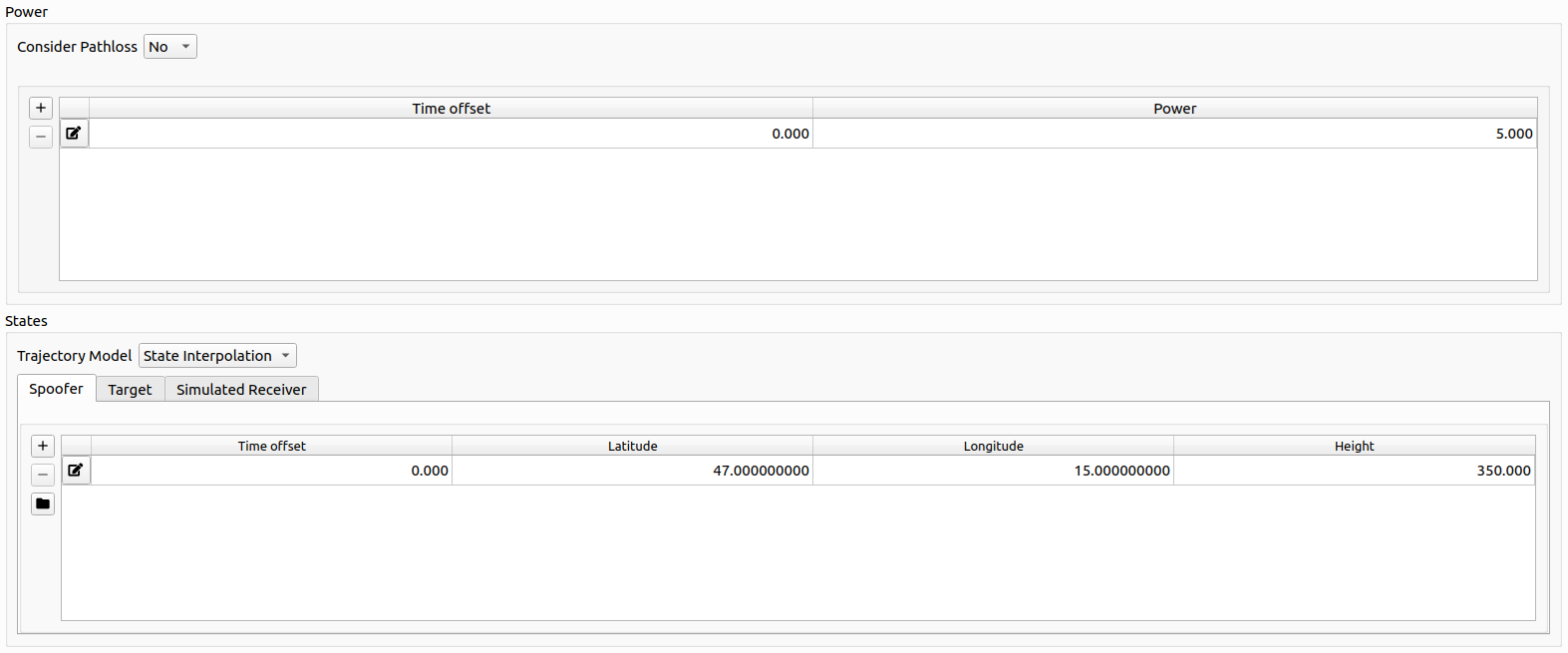
Power:
The table represents a list of time offsets and the corresponding spoofer power in [dB]. Linear Interpolation is applied in between each defined pair of time offset and spoofer power. The power is applied relative to the received authentic signal power of the respective satellite.
State:
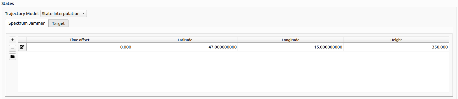
Every state is based upon the same trajectory model introduced in Trajectory Definition.
The three trajectory models are
- Spoofer position
- Simulated receiver position
- Target position
For details, go to Spoofing Trajectory Definition.
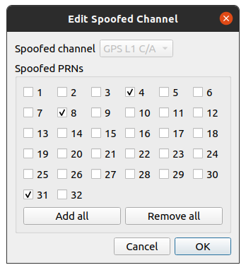
# 3. Spoofer - Channels, spoofed satellites and code offset
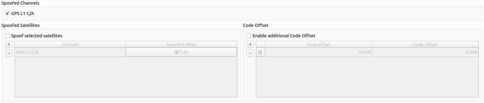
Channels: Determines, which channel the spoofing signals should be generated for.
Note
Only channels that are selected in the general settings section are listed here.
Spoofed Satellites: To fine grain the spoofing process, a narrowed down selection of which satellite per channel should be spoofed. By either clicking on the or the ![]() button, a new spoofed satellite whitelist can be added for a certain channel or a current one can be edited.
button, a new spoofed satellite whitelist can be added for a certain channel or a current one can be edited.
Additional code offset: An additional code offset (pseudorange offset in [m]) can be configured which will be added to each spoofing signal of the respective spoofer. The code offset can be varied over time using a linear interpolation to achieve advanced simulations.