# Receiver
The Receiver settings cover the following receiver based options:
- States
- TLE Orbit
- Clock
- Front-End
- Antennas
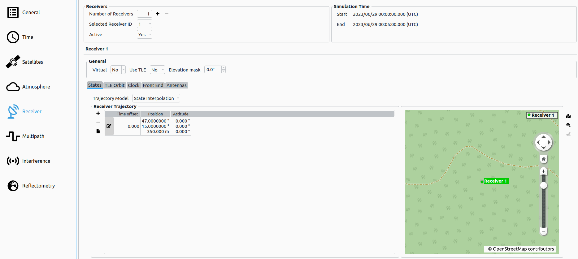
# Receivers Options
| Parameter | Description |
|---|---|
| Number of Receivers (add/remove) | Here the current number of receivers is shown and receivers can be added/removed. |
| Selected Receiver ID | Currently selected receiver. |
| Active | If enabled, the receiver will be simulated (at least one receiver must be active). |
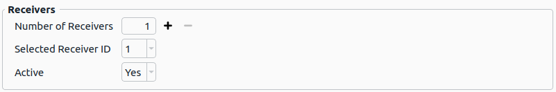
# General Receiver Options
| Parameter | Description |
|---|---|
| Virtual | If enabled, the receiver will be simulated but no authentic signals will be generated for it (only interference signals). |
| Use TLE | If enabled, the receiver trajectory is defined via a TLE dataset instead of the nominal states. |
| Elevation Mask | [°] The receiver's elevation mask can be set here. All satellites with an elevation lower than the set elevation mask angle are not visible and thus are ignored by the simulation (only for observations - the satellite orbits are computed independently from receiver settings). |
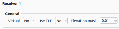
# Receiver States
Additional Information:
- See Trajectory Definition for details.
- See Trajectory Map and Routing for details on how to use the automatic map routing capabilities.
# TLE Orbit
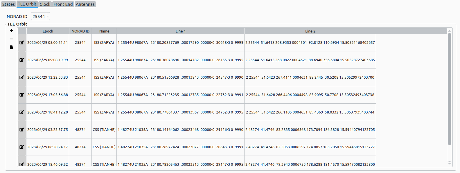
Additionally to the nominal receiver states option, a receiver trajectory can also be defined via a TLE orbit. Various NORAD TLE datasets can be added/imported/edited. Within a table, every dataset with its assigned epoch and ID is displayed. The user can assign the receiver a certain dataset via its ID to define a spaceborne trajectory.
NOTE
If several TLE datasets with the same ID for different epochs exist, the dataset with the nearest epoch to the current simulation epoch will be used to compute the spaceborne receiver state.
Every dataset can be edited  or removed
  or new ones can be added
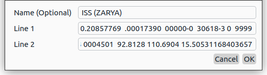
  , by providing inserting the two line strings that define the orbit. In addition, an optional name can be set (Three Line Element).
Furthermore, the user has the option to import TLE orbits from a file by clicking at  . The following file types are supported:
*.txt*.tle*.orbit
NOTE
When importing TLE datasets from a file, it is recommended do directly download the from various providers, e.g. NORAD GP Element Sets (opens new window).
# Receiver Clock
A receiver clock behaviour can be simulated, if desired.
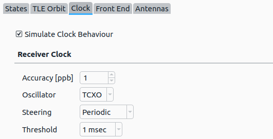
If activated, the following parameters can be configured:
| Parameter | Description |
|---|---|
| Accuracy [ppb] | The LO accuracy (drift) defined as parts per billion. Possible values: -1000 – +1000 |
| Oscillator | Simulated Oscillator (XO, TCXO or OCXO). For more information, see Receiver Clock. |
| Steering | Applying clock steering (None, Continuous or Periodic). If Periodic steering is chosen, a threshold can be set. |
| Threshold | Periodic clock steering threshold (500 usec, 1 msec, 2 msec, 3 msec, 4 msec or 5 msec). |
NOTE
If Receiver Clock is activated, the LO behaviour will not be applied to the generated IF signal.
NOTE
If XPLORA mode is set to Pro, no Receiver Clock settings are available.
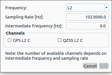
# Front-Ends
NOTE
If XPLORA mode is set to Pro, no Front-End settings are available, since it is handled automatically by the IZT S1000 hardware (see Pro Mode).
Within the table, the bandwidth of the front-end, the IF, as well as ADC parameters can be set. The GIAT module computes the influence of all simulated signals on the tracking loops and furthermore on the raw observations by utilization of the spectral separation coefficient (SSC).
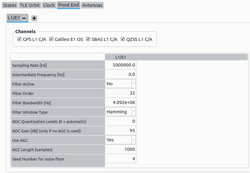
A channel can be added by selecting on the most right tab. This opens the Add Front-End/Channel dialog.
# Front-End options
| Parameter | Description |
|---|---|
| Sampling Rate [Hz] | The sampling rate of the simulated receiver. |
| Intermediate Frequency [Hz] | The used IF within the receiver. |
| Seed Number of Random Signal | Seed for random generator specifying the initial phase of the signal. |
# Filter options
| Parameter | Description |
|---|---|
| Filter Active | If enabled, a front-end filter will be simulated. |
| Filter Order | Filter order of low-pass front-end filter. |
| Filter Bandwidth [Hz] | Filter bandwidth. |
| Filter Window Type | Available values:
|
# ADC options
| Parameter | Description |
|---|---|
| ADC Quantization Levels | Number of quantization levels (has to match number of bits of output configuration, set to '0' for automatic configuration). |
| ADC Gain [dB] | Gain of the ADC. This settings is only used, when Use AGC is set to false. |
| Use AGC | If enabled, an adaptive gain control will be simulated. |
| AGC length | Number of samples considered by AGC. |
# Antennas
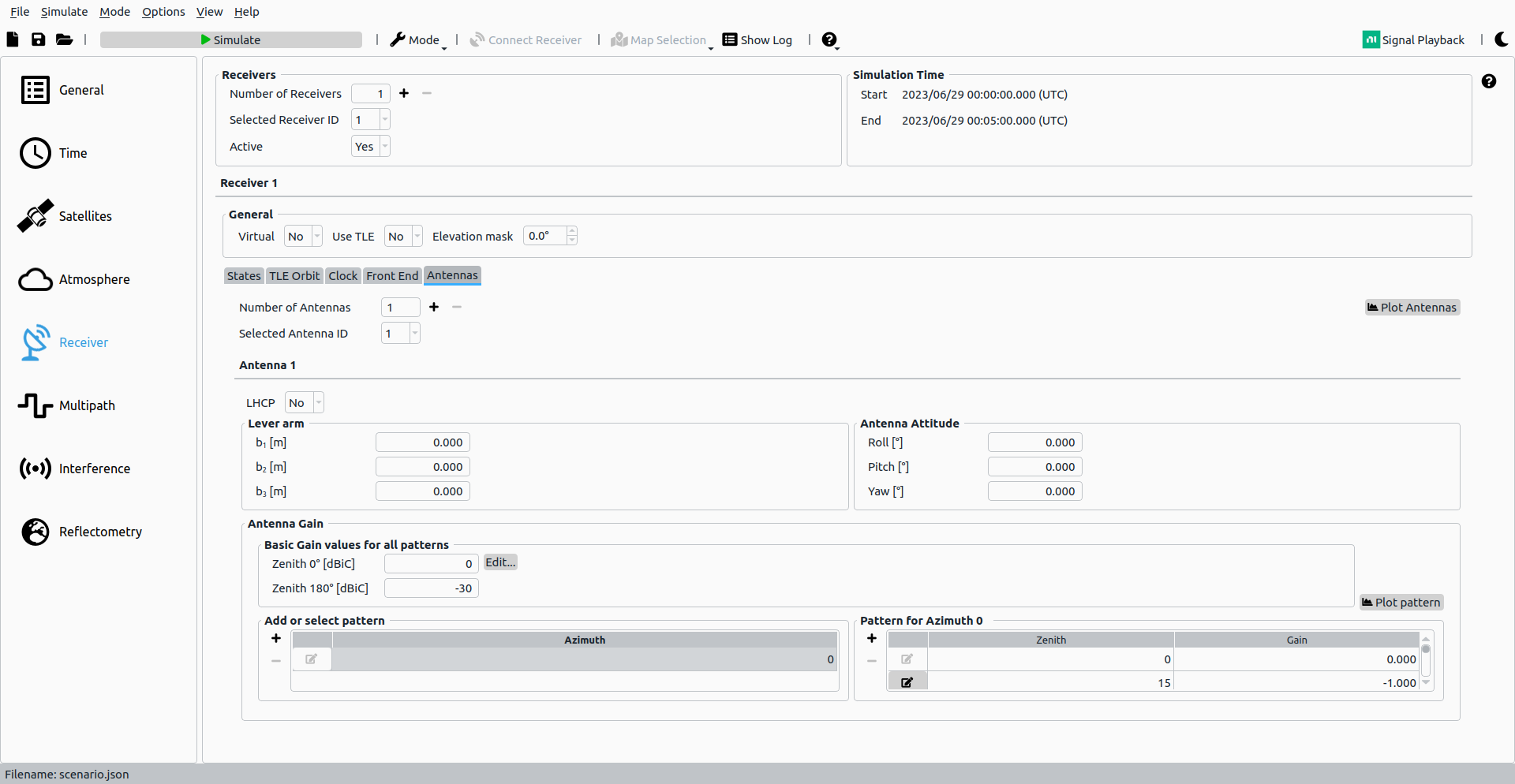
Every receiver can have an unlimited number of antennas defined, all of which are seperatly simulated as IF or RF output.
# LHCP Antenna

Here the polarization of the antenna can be defined. If LHCP is set active, only reflected signals are received by this antenna.
# Lever Arm and Antenna Attitude

Every antenna has a lever arm and an attitude independent from the receivers attitude. For the detailed definition of frames and attitude computation see Receiver Attitude and Antennas.
# Antenna Gain
Within the Antenna Gain parameters tab, an arbitrary antenna pattern can be configured. It offers the possibility to add a maximum of 360 different patterns for each integer azimuth angle (orientation to north). All antenna patterns use common values of gain for a zenith of 0° as well as 180°.
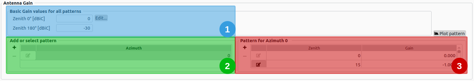
- Basic Gain values: The common gain for an Zenith angle of 0° and 180° can be set here respectively. The pattern is applied for all Azimuths.
- Add or select pattern: The Azimuth for each pattern is presented in this table. The current Azimuth for the table in the highlighted area 3 is selected here. Moreover, additional antenna patterns for other Azimuths can be added/deleted here.
- Pattern for specific Azimuth: The antenna pattern for a singular Azimuth is presented as table. Editing of existing gain values or adding/deleting gain values is possible here.
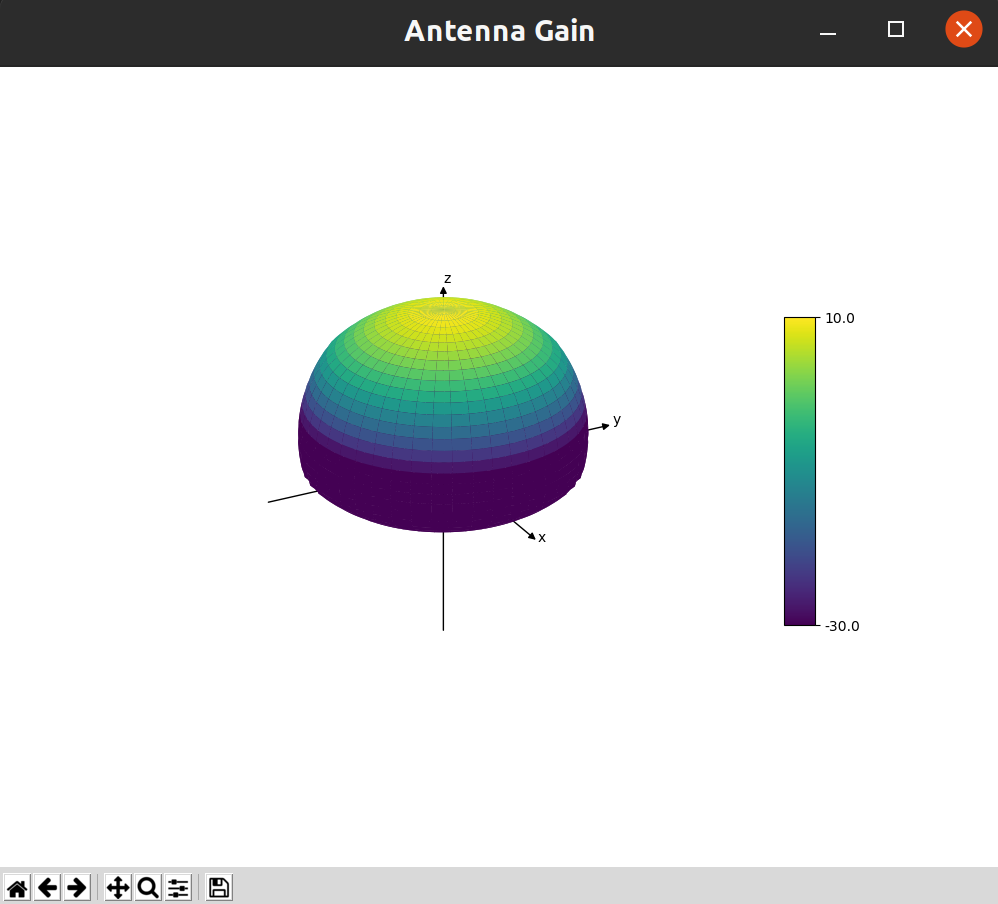
# Plot Pattern
The plot shows the interpolated antenna patterns for each integer Azimuth angle 0°-360° and each Zenith angle 0°-180°.
← Atmosphere Multipath →