# Scenario Simulation
The scenario simulation view shows all relevant information during the run-time of the simulation. This view appears as soon as the simulation has been started. There are two possible simulation views:
- Simulated Receiver: this view shows various information regarding satellites, receivers, etc. and can also be used to apply new scenario settings during run-time.
- Receiver under Test: this view is only available if a receiver is connected. It shows information about the measured trajectory versus the simulated one.
# Simulated Receiver
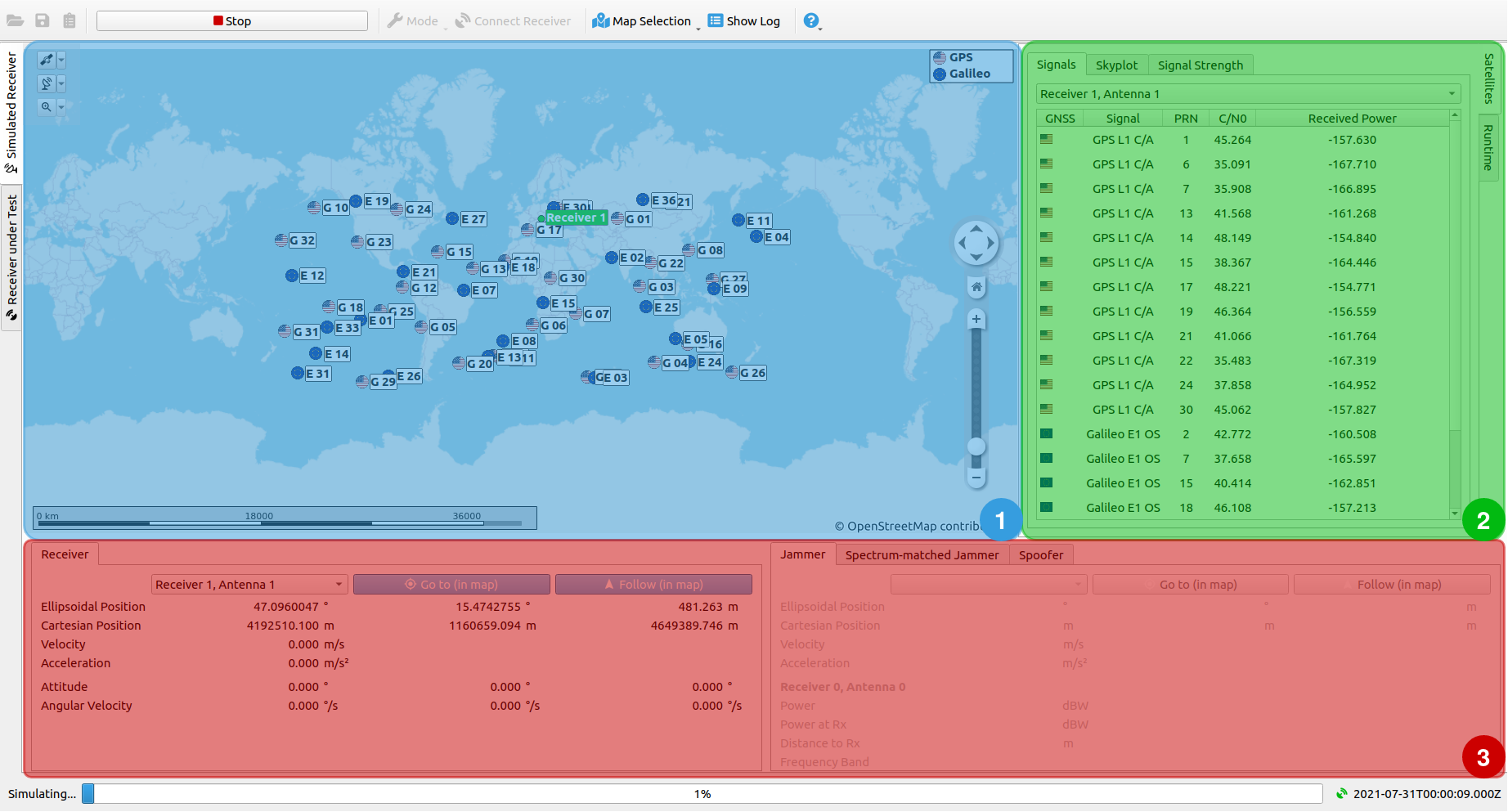
The view consists of 3 sub-windows:
- Map
- Satellite Information and Run-time Input
- Receiver and Interference Information
# Map
The map shows the live-updated positions of the satellites together with the simulated receivers. In case interference has been activated, jammers, spoofers and spoofed positions are displayed as well. In general, two modes of the map can be chosen - Online and Offline (see Menu Bar and Tool Bar for details). The Online Map uses OpenStreetMap as map render and required internet access.
# Map Elements
The map includes some common features such as a zoom and scale bar, a legend on the top right and tool buttons to display several map elements (receivers, satellites) on the top left.

The tool buttons cover three categories:
- GNSS - Show/dismiss satellites of a certain GNSS
- Receiver - Show/dismiss certain receivers or interference objects
- Zoom - Zoom to a certain map object (receiver or interference objects)
# Satellite Information
The Satellite Information section shows relevant information regarding the simulated satellites. Below, a short summary of all Satellite Information tabs is given, describing the information that is displayed to the user. The given tabs are divided into 3 categories:
- Signals
- Skyplot
- Signal Strength
# Signals
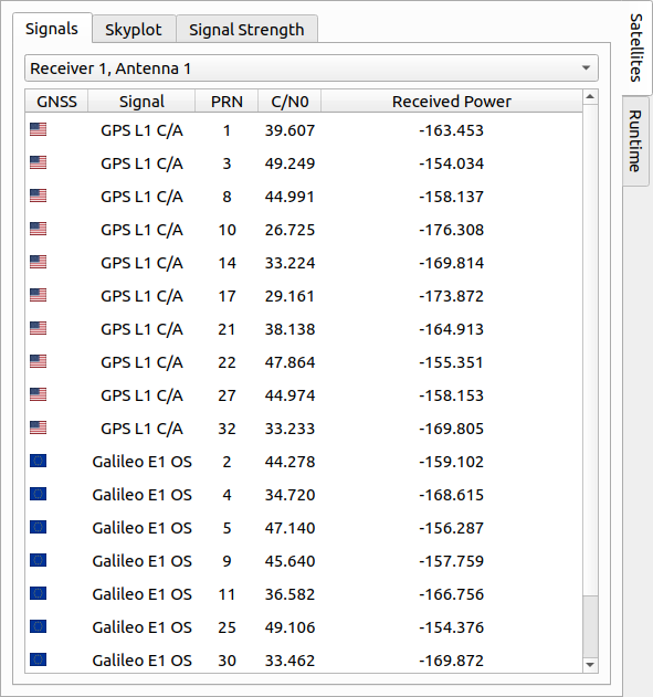
The signals tab lists information for all visible satellites of a receiver. Here, every active receiver can be selected for showing satellite signal information. The following parameters are displayed:
| Parameter | Description |
|---|---|
| GNSS | Country flag representing the GNSS system. |
| Signal | GNSS signal type. |
| PRN | PRN number of the satellite. |
| C/N0 | Received CNR of the satellite signal in [dB-Hz]. |
| Received Power | Received power of the satellite signal in [dBW]. |
# Skyplot
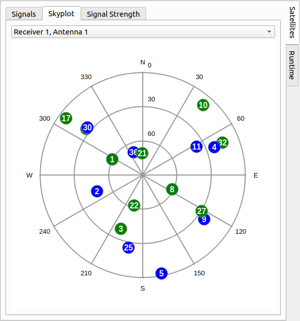
The Skyplot tab plots the current distribution of the satellites over the sky for every individual receiver. Here, the azimuth and elevation angle can be determined for each satellite in respect to the selected receiver.
# Signal Strength
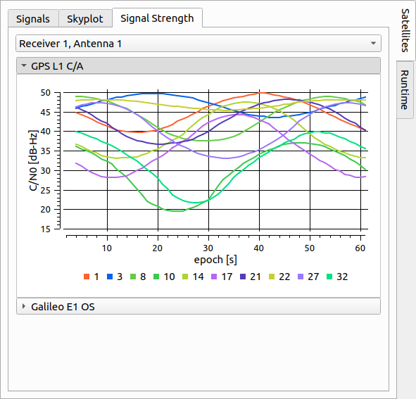
The Signal Strength tab displays a time-series of the satellites' CNR values for each GNSS signal. The time-series plot is updated live during simulation run-time. For every selected receiver and every GNSS signal type a time-series plot can be displayed.
# Run-time Input
Inside the Run-time Input section, the current settings for certain simulation objects (e.g. receivers, satellites, ...) can be queried, changed and directly applied during run-time. In the following, all applicable settings within the Run-time Input section are described. The 5 categories, where parameters can be applied, are as follows:
- Receiver
- Satellites
- Multipath
- Jammer
- Spoofer
- Spectrum-matched Jammer
NOTE
XPLORA also offers an API, where run-time settings can be applied over a TCP/IP connection. This is useful for HIL setups. For more information, see Run-time API.
# Receiver
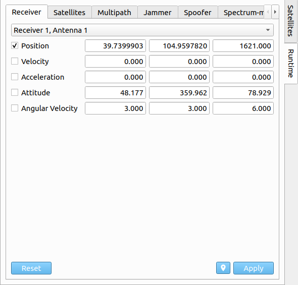
Within the Receiver tab, the current state (e.g. position, velocity, acceleration) and attitude (e.g. attitude and angular-velocity) of a selected receiver can be adapted. Via the ![]() button, the current receiver state can be queried. The receiver state can be changed by inserting new values for the individual vector components. In order to apply any of the new values, the checkbox on the left side of each changeable setting can be individually de-/activated. After that, the user can directly apply the new input, by pressing the
button, the current receiver state can be queried. The receiver state can be changed by inserting new values for the individual vector components. In order to apply any of the new values, the checkbox on the left side of each changeable setting can be individually de-/activated. After that, the user can directly apply the new input, by pressing the  button on the bottom right. In order to reset the new input data, press the
  button.
The definition of the state vector format is described in the section Trajectory Definition. In case, state interpolation as Receiver Path model was initially set in the scenario settings and a new receiver state has been applied during run-time, the model switches to state propagation.
| Parameter | Description |
|---|---|
| Active | Active flag of satellite. |
| Health | Health flag of satellite. |
| Power | Transmitting power of satellite in [dBW]. |
# Satellites
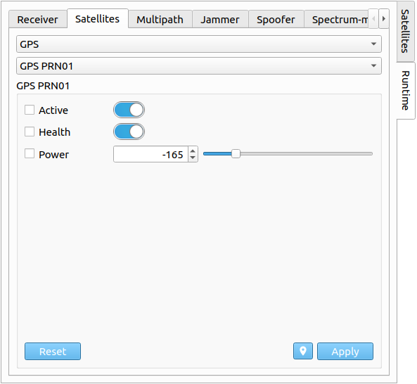
In the Satellites tab, individual satellites can be de-/activated, set un-/healthy and the transmitting signal power can be adapted as well. Each satellite of every GNSS system can be selected. The transmitting power can either be changed via a slider, or via a spinbox. In order to apply any new settings/configurations, the checkbox on the left side needs to be enabled for each individual setting.
# Multipath
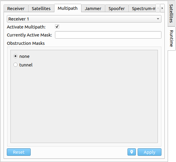
In the Multipath tab, multipath effects within the receiver can be activated or deactivated. Moreover, the currently active obstruction mask can be queried and changed. A new obstruction mask can be chosen from a list of predefined ones. More information on predefined obstruction masks can be found at Multipath. In order to apply any new settings/configurations, the checkbox on the left side needs to be enabled for each individual setting.
# Jammer
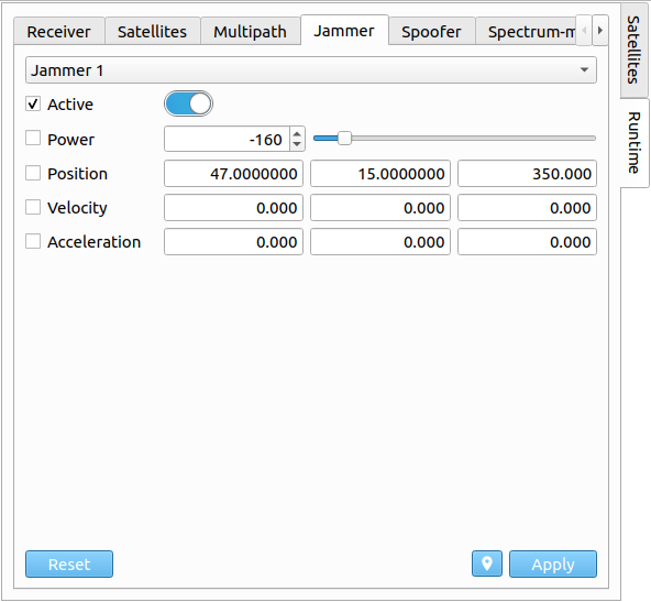
Via the Jammer tab, the selected jammer's state can be changed together with the transmitting power. The transmitting power can either be changed via a slider, or via a spinbox. Furthermore, the jammer can be switched on/off. The jammer state format and application is the same as described in Receiver section. In order to apply any new settings/configurations, the checkbox on the left side needs to be enabled for each individual setting.
| Parameter | Description |
|---|---|
| Active | Active flag of jammer. |
| Power | Transmitting power of jammer in [dBW]. |
| Jammer State | State vector of jammer. |
Note
The jammer state format and application is the same as described in Receiver section.
# Spoofer
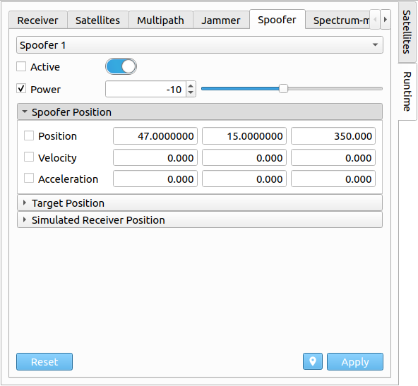
Via the Spoofer tab, the selected spoofer's states (spoofer, target and simulated receiver state) can be changed together with the transmitting power. The transmitting power can either be changed via a slider, or via a spinbox. Furthermore, the spoofer can be switched on/off. In order to apply any new settings/configurations, the checkbox on the left side needs to be enabled for each individual setting.
| Parameter | Description |
|---|---|
| Active | Active flag of spoofer. |
| Power | Transmitting power of spoofer in [dB]. |
| Spoofer State | State vector of spoofer. |
| Target State | State vector of target. |
| Sim. Receiver State | State vector of simulated receiver. |
Note
- The spoofer state format (Spoofer State, Target State & Simulated Receiver State) and application is the same as described in Receiver section.
- See Spoofer Trajectory Definition for details on the individual spoofer states.
# Spectrum-matched Jammer
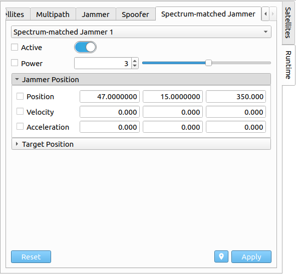
Via the Spectrum-matched Jammer tab, the selected spectrum jammer's states (jammer and target state) can be changed together with the transmitting power. The transmitting power can either be changed via a slider, or via a spinbox. Furthermore, the spectrum jammer can be switched on/off. In order to apply any new settings/configurations, the checkbox on the left side needs to be enabled for each individual setting.
| Parameter | Description |
|---|---|
| Active | Active flag of spectrum jammer. |
| Power | Transmitting power of jammer in [dB]. |
| Jammer State | State vector of spectrum jammer. |
| Target State | State vector of target. |
Note
- The spectrum-matched jammer state format (Jammer State & Target State) and application is the same as described in Receiver section.
- See Spectrum-matched Jammer Trajectory Definition for details on the individual spectrum jammer states.
# Receiver and Interference Information
The Receiver and Interference Information section shows relevant information regarding the simulated receivers and in case of active intentional interference settings, also the simulated jammers and spoofers. Every information tab (Receiver, Jammer and Spoofer) has the same base structure, where in the top row, any one of the predefined receivers/interference objects (active and non-active) can be chosen via selection. Furthermore, the map's focus on a certain object can be set. In case the object is moving, it can also be automatically followed within the map.
# Receiver
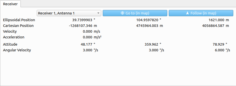
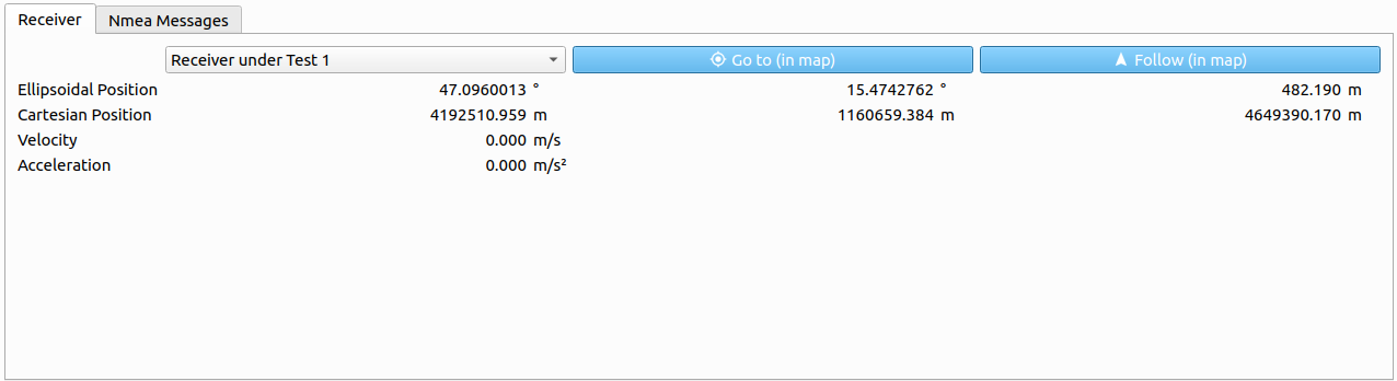
The following parameters are displayed for a chosen receiver:
| Parameter | Description |
|---|---|
| Ellipsoidal Position | Ellipsoidal position vector (WGS84, in [deg] and [m]). |
| Cartesian Position | Cartesian position vector (WGS84, in [m]). |
| Velocity | Absolute velocity within the LLF in [m/s]. |
| Acceleration | Absolute acceleration within the LLF in [m/s²]. |
# Jammer
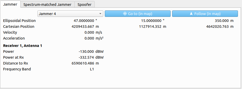
The following parameters are displayed for a chosen jammer:
| Parameter | Description |
|---|---|
| Ellipsoidal Position | Ellipsoidal position vector (WGS84, in [deg] and [m]). |
| Cartesian Position | Cartesian position vector (WGS84, in [m]). |
| Velocity | Absolute velocity within the LLF in [m/s]. |
| Acceleration | Absolute acceleration within the LLF in [m/s²]. |
| Power | Transmitting power in [dBW]. |
| Power at Rx | Received power at receiver side in [dBW]. |
| Distance to Rx | Distance to receiver in [m]. |
| Frequency Band | Frequency band of the jammer. |
Note
The receiver dependent parameters are always with respect to the currently chosen receiver within the Receiver tab on the left side of the Receiver/Interference Information section.
# Spectrum-matched Jammer
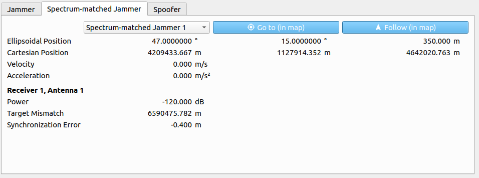
The following parameters are displayed for a chosen spectrum-matched jammer:
| Parameter | Description |
|---|---|
| Ellipsoidal Position | Ellipsoidal position vector (WGS84, in [deg] and [m]). |
| Cartesian Position | Cartesian position vector (WGS84, in [m]). |
| Velocity | Absolute velocity within the LLF in [m/s]. |
| Acceleration | Absolute acceleration within the LLF in [m/s²]. |
| Power | Transmitting power in [dB]. |
| Target Mismatch | Determines the synchronization error for the PRN code based on the current receiver position and the current target position [m] |
| Sync. Error | The synchronization error from the Gaussian Normal Distribution. [m] |
# Spoofer
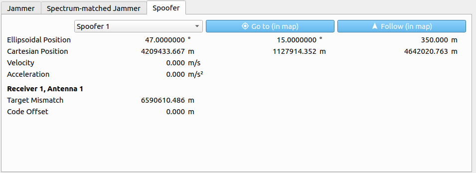
The following parameters are displayed for a chosen spoofer:
| Parameter | Description |
|---|---|
| Ellipsoidal Position | Ellipsoidal position vector (WGS84, in [deg] and [m]). |
| Cartesian Position | Cartesian position vector (WGS84, in [m]). |
| Velocity | Absolute velocity within the LLF in [m/s]. |
| Acceleration | Absolute acceleration within the LLF in [m/s²]. |
| Power | Transmitting power in [dB]. |
| Code Offset | Additional code-offset applied to spoofed signals in [m]. |
| Target Mismatch | Distance between target position and simulated receiver position in [m]. |
Note
The receiver dependent parameters are always with respect to the currently chosen receiver within the Receiver tab on the left side of the Receiver/Interference Information section.
# Receiver under Test
This simulation view is available if a receiver is configured in the
Configuration Dialog. The so called Receiver under Test obtains the simulated signal and forwards it via NMEA messages during the simulation.
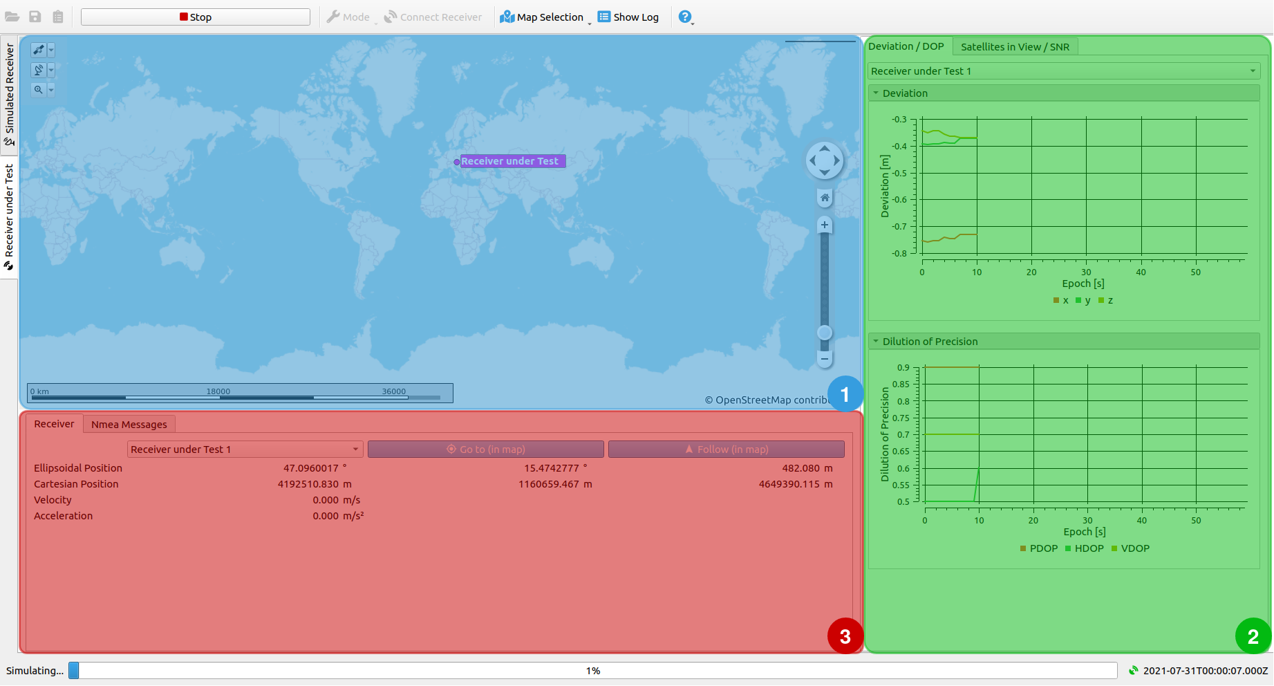
The view consists of 3 sub-windows:
- Map
- Visualization of Receiver under Test versus Simulated Receiver
- Receiver Information and NMEA Messages
# Map
The map shows the live-updated positions of the Receiver under Test.
# Visualization of Receiver under Test versus Simulated Receiver
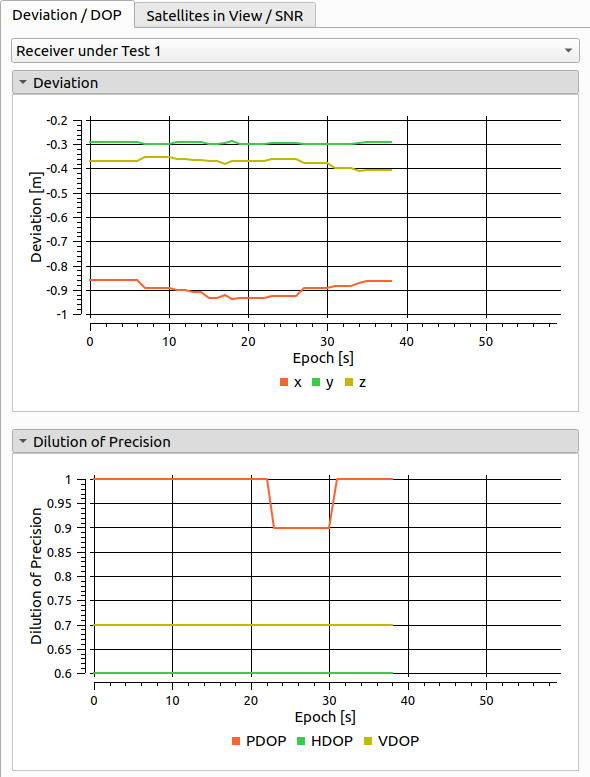
# Deviation and DOP
Information for the Deviation plot is read from NMEA GGA messages and shows the difference of the simulated and the measured receiver trajectory. The DOP plot shows the Dilution of precision, provided by NMEA GSA messages.
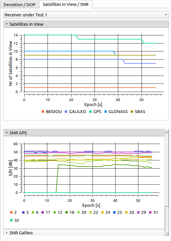
# Satellites in View and SNR
The Satellites in View plot shows the number of currently visible satellites for each GNSS system. For each GNSS system a SNR plot shows the signal to noise ratio of each visible satellite. Information for these plots are read from NMEA GSV messages.
# Receiver Information and NMEA Messages
# Receiver
The Receiver Information tab shows relevant information regarding the connected Receiver under Test.
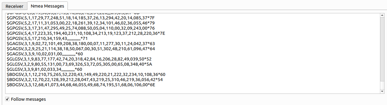
# NMEA Messages
This tab shows the received NMEA Messages for each epoch.