# Interference
The Interference settings cover the following options:
- Jammer Settings
- Spectrum-matched Jammer Settings
- Spoofer Settings
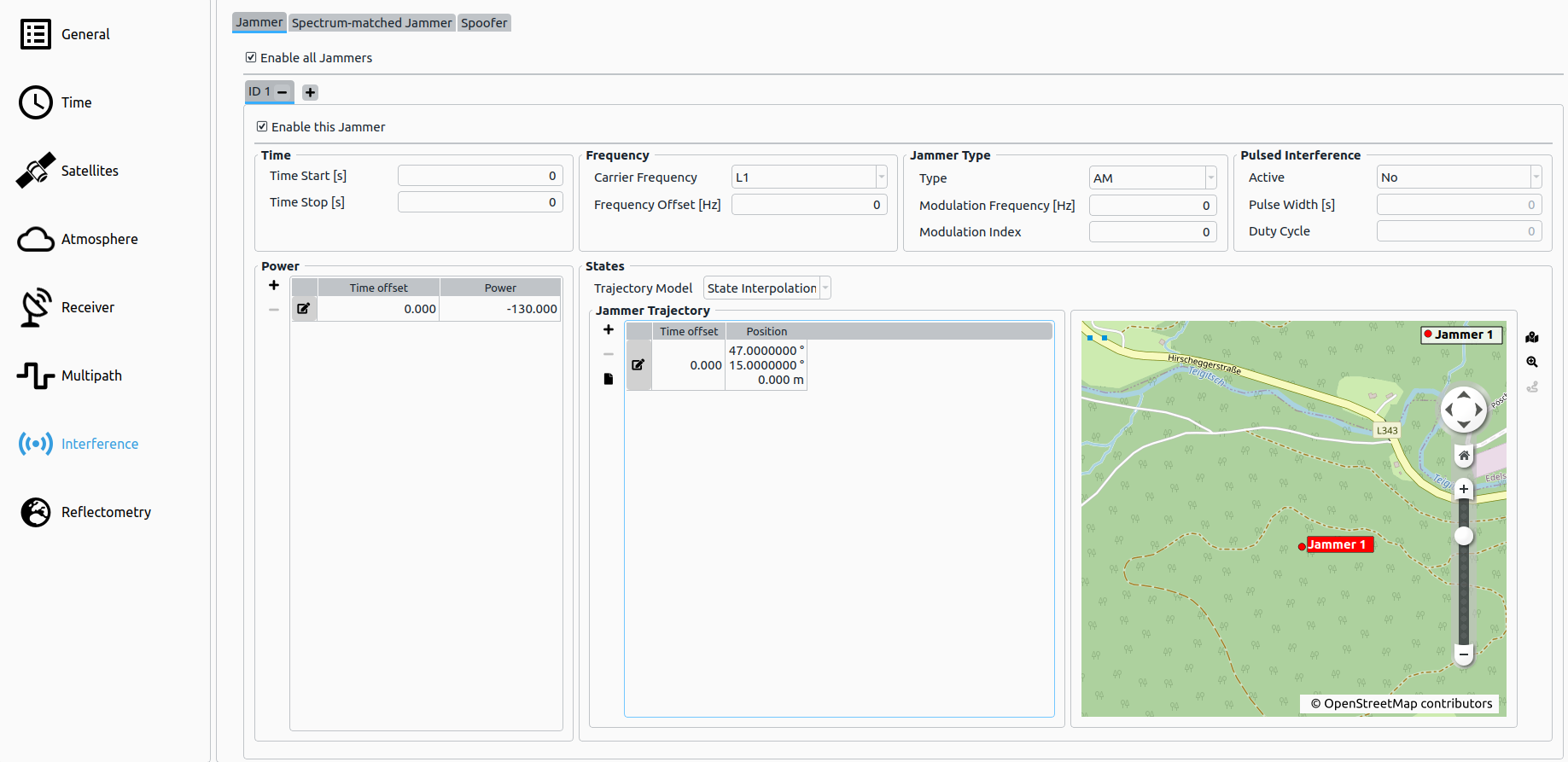
# Jammer
The Jammer tab displays the options in order to compute the influence of the interferers on the tracking loops (thus the output CNR as well as the noise within the tracking loops is changed). The interference signals are added to the IF signal in XPLORA Core mode and are directly broadcasted by the IZT S1000 hardware in Pro mode.
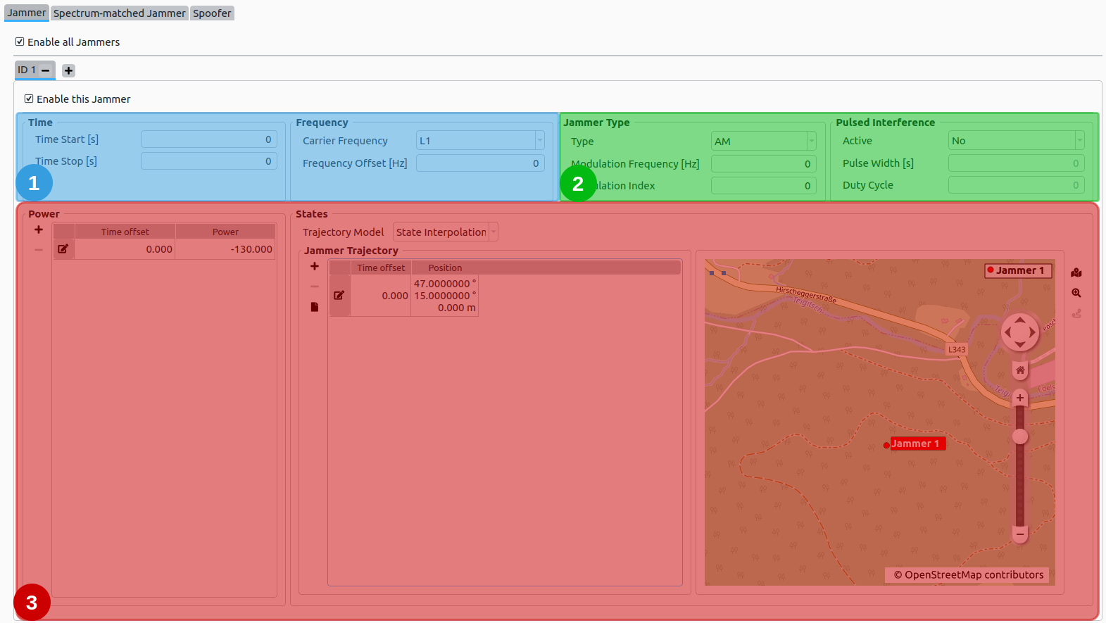
The Jammer tab is divided into three different sections:
# 1. Jammer – Time and Frequency
Time: Determines the time-span, where the jammer is simulated and applied.
| Parameter | Description |
|---|---|
| Time start | Time offset [s] relative to the scenario start epoch. |
| Time end | Time offset [s] relative to the scenario start epoch. Has to be larger than Time start. |
Frequency:
| Parameter | Description |
|---|---|
| Carrier Frequency | The carrier frequency the Jammer is simulated on. See Carrier Frequencies. |
| Frequency Offset [Hz] | The frequency offset from the carrier frequency. |
Note
The Jammer is only simulated if the corresponding channel was selected in the general settings section.
# 2. Jammer – Type and Pulsed Interference
Type:
The following Jammer Types and their according parameters can be set:
| Type | Parameters |
|---|---|
| AM (Amplitude Modulation) |
|
| FM (Frequency Modulation) |
|
| SCW (Swept Continuous Wave) |
|
| WGN (White Gaussian Noise) |
|
Pulsed Interference:
| Parameter | Description |
|---|---|
| Active | Defines, if the jamming signal is pulsed or not. |
| Pulse Width | Defines the width of a single pulse [s] (only available, if pulsed interference is enabled). |
| Duty Cycle | The percentage of time, which is occupied by a pulse (between 0.0 and 1.0). |
# 3. Jammer – Power and State
Power:
The table represents a list of time offsets and the corresponding jammer power. Linear Interpolation is applied in between each defined pair of time offset and jammer power.
State:
The Jammer state. Additional Information:
- See Trajectory Definition for details.
- See Trajectory Map and Routing for details on how to use the automatic map routing capabilities.
# Spectrum-matched Jammer
The Spectrum-matched jammer tab offers the possibility to add spectrum-matched jamming signals to the simulated signal. Several spectrum-matched jammers can be configured.
The spectrum-matched jammer adds an additional GNSS signal for each satellite in view. Jamming is achieved by transmitting the signal with only the PRN code added to the signal and therefore omitting the navigation message. In addition, each code delay is altered by a synchronization error which is user determinable in contrast to the authentic code delays.
For a detailed description of the mathematical model applied see Spectrum-matched Jammer definition
- Spectrum-matched Jammer – Time
- Spectrum-matched Jammer – General
- Spectrum-matched Jammer – Power and State
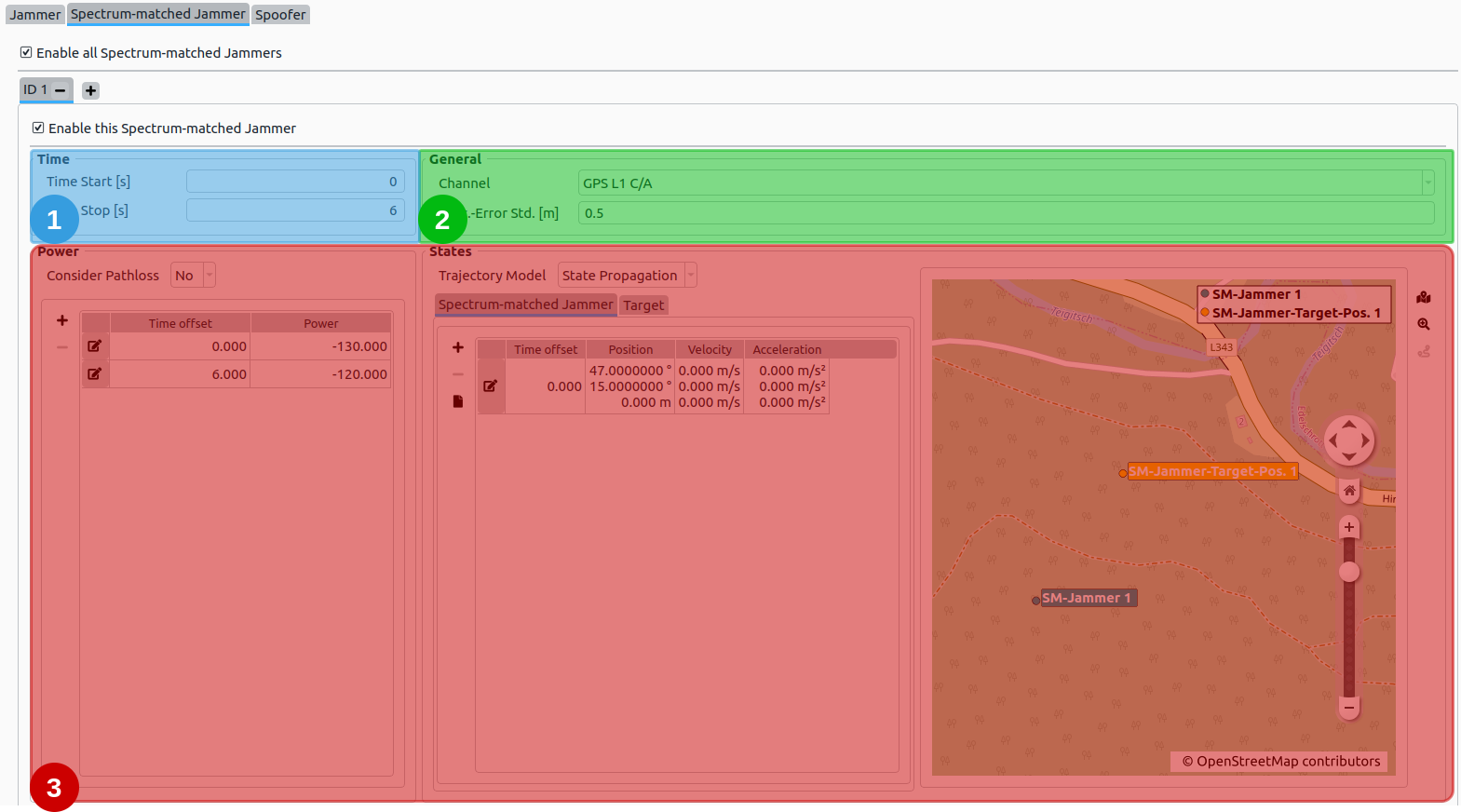
# 1. Spectrum-matched Jammer – Time
Time: it determines, when the spectrum-matched jammer is simulated.
| Parameter | Description |
|---|---|
| Time start | Time offset [s] relative to the scenario start epoch. |
| Time end | Time offset [s] relative to the scenario start epoch. Has to be larger than Time start. |
# 2. Spectrum-matched Jammer – General
General Options:
| Parameter | Description |
|---|---|
| Channel | Determines which channel is jammed. Only one channel per spectrum-jammer can be jammed, and only a channel that is chosen in the General Settings tab can be selected. |
| Synchronization Error Standard Deviation | [m] |
# 3. Spectrum-matched Jammer – Power and State
Power:
| Parameter | Description |
|---|---|
| Consider Pathloss | The received power of the jamming signal (relative to authentic signals) shall be computed based on path loss or not. |
The table represents a list of time offsets and the corresponding spectrum-matched jammer power in [dB]. Linear Interpolation is applied in between each defined pair of time offset and jammer power. The power is applied relative to the received authentic signal power of the respective satellite.
State:
Every state is based upon the same trajectory model introduced in Trajectory Definition.
The two trajectory models are
- Spectrum-matched Jammer position
- Target position
For details, go to Spectrum-matched Jammer Trajectory Definition.
Additional Information:
- See Trajectory Definition for details.
- See Trajectory Map and Routing for details on how to use the automatic map routing capabilitites.
# Spoofer
The Spoofer tab offers the possibility to add spoofed GNSS signals to the IF signal in XPLORA Core mode and to the RF signal in Pro mode. Several spoofers can be configured.
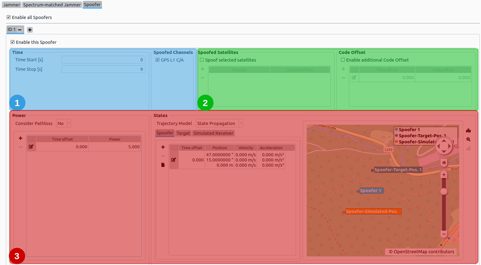
The Spoofer tab is divided into three different sections:
- Spoofer – Time and Spoofed Channels
- Spoofer – Spoofed Satellites and Code Offset
- Spoofer – Power and State
# 1. Spoofer – Time and Spoofed Channels
Time: it determines, when the spoofer is simulated.
| Parameter | Description |
|---|---|
| Time start | Time offset [s] relative to the scenario start epoch. |
| Time end | Time offset [s] relative to the scenario start epoch. Has to be larger than Time start. |
Spoofed Channels: Determines, which channel the spoofing signals should be generated for.
Note
Only channels that are selected in the general settings section are listed here.
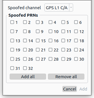
# 2. Spoofer – Spoofed satellites and Code Offset
Spoofed Satellites: To fine grain the spoofing process, a narrowed down selection of which satellite per channel should be spoofed. By either clicking on the  or the
  button, a new spoofed satellite whitelist can be added for a certain channel or a current one can be edited.
Code Offset: An additional code offset (pseudorange offset in [m]) can be configured which will be added to each spoofing signal of the respective spoofer. The code offset can be varied over time using a linear interpolation to achieve advanced simulations.
# 3. Spoofer – Power and State
Power:
The table represents a list of time offsets and the corresponding spoofer power in [dB]. Linear Interpolation is applied in between each defined pair of time offset and spoofer power. The power is applied relative to the received authentic signal power of the respective satellite.
State:
Every state is based upon the same trajectory model introduced in Trajectory Definition.
The three trajectory models are
- Spoofer position
- Simulated receiver position
- Target position
For details, go to Spoofing Trajectory Definition.
Additional Information:
- See Trajectory Definition for details.
- See Trajectory Map and Routing for details on how to use the automatic map routing capabilities.